Bullhorn Model RM4014 & RM4015 Remote Monitors by American Innovations
Description
The RM4014 and RM4015 are satellite-based, reliable, two-way, wireless remote monitoring units (RMUs) for cathodic protection applications, and they’re Built Bullhorn Tough. The only difference between these units is that the RM4014 is mounted externally, while the RM4015 is small enough to fit inside most rectifier cabinets. Otherwise, both units have the same functionality.
These units monitor pipelines, well casings, tanks and other assets by reading rectifier AC and DC volts and amps, pipe-to-soil potential, shunts, and more. Additionally, they can survive the harshest of conditions, with built in surge protection and an optional high-energy surge arrester.
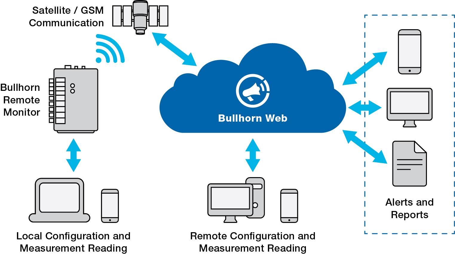 The RM4014 and RM4015 remotely collect cathodic protection (CP) measurements used to demonstrate corrosion mitigation effectiveness. They monitor pipelines, well casings, tanks and other assets by reading rectifier AC and DC volts and amps, pipe-to-soil potential, shunts, and more. GPS synchronized interruption is available at time of purchase or as a field upgrade. The Orbcomm IsatData Pro satellite network is used for global, low-latency, two-way communications. Measurements are automatically uploaded to Bullhorn Web, a web-based asset manager that works with PCS™ to form a full end-to-end regulatory compliance solution from field measurement to reporting. The RM4014 is mounted externally, while the RM4015 is small enough to fit inside most rectifiers.
Key Benefits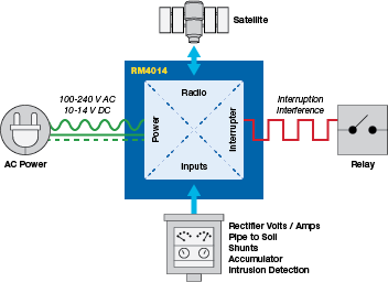
- Rugged – The unit can survive the harshest of conditions, with built in surge protection and optional high energy surge arrester.
- Small – Reduce installation time and the risk of vandalism by placing the remote monitoring unit inside the rectifier.
- Remotely Operated via the Web and Mobile – Never have to leave the office to operate a unit, as the mobile and web apps can be used to change configuration, take a measurement, and control interruption.
- Integrated Compliance Solution – Complete end-to-end system to prove regulatory compliance, with filtered measurements easily imported into PCS where they can be made into compliance reports
| Feature | Benefit |
| Analog channels measure both AC and DC Potentials | Single unit to measure rectifier volts and amps, pipe-to-soil potential, shunts, and more |
| Two percent of reading accuracy | Extremely accurate current and voltage measurements |
| Digital channels provide discrete/close contact inputs and accumulator functionality | The unit can also be used for intrusion detection, threshold detection and other state changes as well as pulse counting for metering |
| 10 MΩ impedance | Improved pipe-to-soil accuracy where just a few mA can be the difference between being in compliance and not |
| Pipeline Compliance System (PCS) integration | Import RMU data directly or file transfer using Bullhorn Web |
| Global coverage via Orbcomm IsatData Pro satellite network | Quickly communicate anywhere in the world without having to estimate coverage as required with cellular-based products |
| Two-way communication | Within seconds poll, reconfigure, modify reporting schedules, set alarm thresholds and update firmware over-the-air |
| Sends alarms based on specific events (e.g. reading out of range, power loss, intrusion detection, etc.) | Receive unlimited notifications via text message, email, and voice |
| Configurable over-the-air via Bullhorn Web or locally via USB |
|
| Optional built-in GPS synchronized interruption |
|
| Unique Interference Mode interruption for influence studies is compatible with the RM4150, RM4151, MicroMax GPS 300, and GPS350 interrupters |
|
| Bullhorn Web system communicates unit status by email, text, or web notifications |
|
| Internal backup battery | Receive alarms when power fails |
| More than 6.6 kV built-in surge protection per IEC 61000-4-5 specification | Increase product reliability with immunity to lightning and other surges |
Specifications
| Inputs |
| 4 Analog Channels |
| Channels 1, 3, 4 DC voltage range: +/- 5 V |
| Channels 2 DC voltage range: +/- 100 V |
| Accuracy of 2% of reading |
| Scan rate: sampled every 16 seconds |
| Channel-to-channel isolation: ≥ 250 V DC |
| 2 Digital Channels |
| Functions: digital input, accumulator, accumulator reset, or contact closure (0 - 15 V DC) |
| Logic levels: minimum Logic 1 = 2 V; maximum Logic 0 = 800 mV |
| Scan rate: once every second |
| Accumulator maximum cycle rate = 1 cycle/2 s; minimum state change period = 1 s |
| Minimum pulse width: 250 ms |
| Interruption Option |
| Maximum current: 500 mA DC |
| Output voltage: 10 – 14 V DC |
| Minimum switching cycle: 1 s |
| On/off cycle increments: 100 ms |
| Interruption modes: daily, interference, start/stop, and continuous |
| Interference mode: set up to 99 rectifiers or groups for influence studies |
| Relay types: NO or NC, solid state or mechanical |
| Communications |
| Orbcomm – IsatData Pro |
| Poll, reconfigure, and set alarm thresholds over-the-air |
| Software Interface |
| Bullhorn Web |
| Bullhorn Tools for PC |
| Power Supply |
| AC: 100 - 240 V AC with included AC/DC converter |
| DC: 10 - 14 V DC with interruption; 5-25 V DC without interruption |
| Backup: internal sealed rechargeable battery |
| Dimensions |
| Internal mount: polycarbonate enclosure (7.9” x 5.0” x 2.2”) |
| External mount: NEMA 4X compliant enclosure (4.0” x 7.3” x 12.4”) |
| Data Integrity |
| Data stored in non-volatile (EEPROM) memory. |
| Environment |
| Temperature: -30° C to +70° C |
| Humidity: 0 - 100% non-condensing |
| Compliance |
| Certification mark: TUV |
|
Tested safety standards (RM4010 only):
|
| ESD: 8kV Air / 4 kV Contact |
| Emissions: FCC part 15 |