By continuing to browse this website or by clicking 'I Accept', you agree to the use of cookies. Cookies are stored on your computer or mobile device and enhance your site experience. To learn more about how we use cookies, you can click the 'Learn More' button.
Model FE Through-wall, Extreme Environment Reference Electrode by EDI
For use in Oil Separators, Heater Treaters, or other Process Vessels
Description
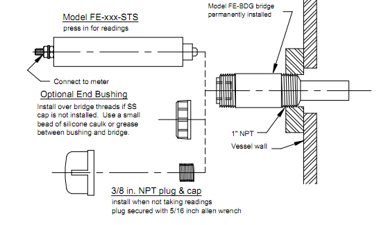
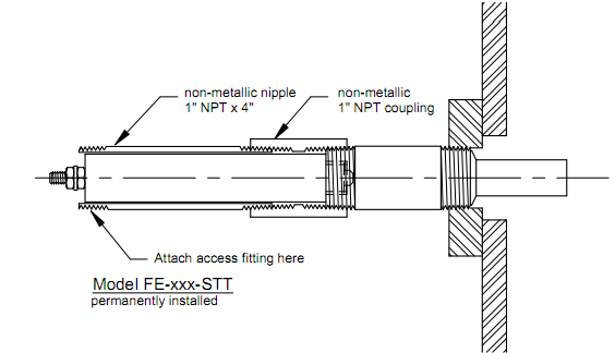
The Model FE is designed to operate in extreme environments with high temperatures, high pressures and / or contaminated electrolytes where ordinary reference electrodes cannot survive. A permanent bridge is installed at each location where potential readings are desired. The reference element is contained in a separate housing which isolates it from the aggressive environment; this substantially increases its service life. When continuous readings are required, the reference is threaded into the bridge. For intermittent readings, the reference is simply pressed into the bridge. This allows a single reference to be used with several bridges. Further details are shown on the following pages.
Typical Applications
Oil separators, heater treaters, bleach tanks, industrial boilers and process vessels.
Features
Two-piece design which isolates the reference element from the environment.
Permanently installed bridge fabricated from G-10 (a glass reinforced epoxy) should not need replacing.
Removable CPVC housing which contains the reference element.
Bridge Specifications
1" NPT x 3" SS nipple
3/4" dia G-10 extension, length to suit
3/8" NPT-F junction well
Pressure rated to 50 psi
Max. process side temp. +200oF
Body Specifications
1" dia x 5 " CPVC body with smooth or threaded junction
Smooth - Slip-fit junction
Threaded - 3/8" NPT-M junction
1/4-20 x ½" threaded stud termination
Element Types
AGG - Saturated gelled Ag / AgCl
CUG - Saturated gelled Cu / CuSO4
Operating Instructions
The Model FE reference electrode consists of two pieces:
The bridge which is permanently installed in the vessel, and
The reference which can be either permanently installed or temporarily inserted when measurements are required.
All bridges are factory tested to 150 psi. The bridge is designed to leak slightly in service to ensure good conductivity; the quantity of liquid emitted will be proportional to the pressure differential across the bridge.
Temporary Electrode Installation
In a temporary installation, the reference electrode is inserted into the bridge whenever a potential measurement is required. In between readings, the 3/8" pipe plug must be installed in the bridge; at pressures over 50 psi, the 1" end cap must also be used. If the plug and cap are installed without any joint compound or gaskets, the bridge will leak slightly to relieve the pressure buildup. If a leak-free installation is required, use Teflon tape or a non-hardening Teflon pipe dope on the threads.
Whenever the end cap or pipe plug is removed, it should be assumed that the liquid behind it is under pressure. The cap should be slowly loosened to bleed off the pressure; once the leakage has stopped, the cap can be removed. The same procedure must be repeated when removing the plug.
Permanent Electrode Installation
For maximum electrode life, the electrode should be installed into the bridge using no pipe thread sealants or gaskets. A small amount of liquid will leak from the joint preventing a pressure buildup inside the bridge. Should a leak-free joint be required, then the appropriate sealants and the supplied gasket can be used. Note, however, that if the gasket is used, the bridge will be operating at the vessel pressure which can force some of the vessel contents into the electrode and shorten its life.
To replace a permanently installed electrode, it is not necessary to drain the vessel since the bridge remains permanently installed. Loosen the electrode just enough for the joint to start leaking which will relieve any pressure at the end of the bridge. When the leaking stops, continue to slowly unscrew the electrode until it is removed. A new electrode can then be installed.
Safety Precautions
Appropriate safety equipment as required by the vessel contents and pressure must be used whenever the pipe plug, end cap or electrode is removed from the bridge. At a minimum, suitable eye protection must be used even if the vessel only contains water. It is always possible that a small amount of liquid will spray out under pressure when the plug, cap or electrode is first loosened.
Description
The Model FE is designed to operate in extreme environments with high temperatures, high pressures and / or contaminated electrolytes where ordinary reference electrodes cannot survive. A permanent bridge is installed at each location where potential readings are desired. The reference element is contained in a separate housing which isolates it from the aggressive environment; this substantially increases its service life. When continuous readings are required, the reference is threaded into the bridge. For intermittent readings, the reference is simply pressed into the bridge. This allows a single reference to be used with several bridges. Further details are shown on the following pages.
Typical Applications
Oil separators, heater treaters, bleach tanks, industrial boilers and process vessels.
Features
Two-piece design which isolates the reference element from the environment.
Permanently installed bridge fabricated from G-10 (a glass reinforced epoxy) should not need replacing.
Removable CPVC housing which contains the reference element.
Bridge Specifications
1" NPT x 3" SS nipple
3/4" dia G-10 extension, length to suit
3/8" NPT-F junction well
Pressure rated to 50 psi
Max. process side temp. +200oF
Body Specifications
1" dia x 5 " CPVC body with smooth or threaded junction
Smooth - Slip-fit junction
Threaded - 3/8" NPT-M junction
1/4-20 x ½" threaded stud termination
Element Types
AGG - Saturated gelled Ag / AgCl
CUG - Saturated gelled Cu / CuSO4
Operating Instructions
The Model FE reference electrode consists of two pieces:
The bridge which is permanently installed in the vessel, and
The reference which can be either permanently installed or temporarily inserted when measurements are required.
All bridges are factory tested to 150 psi. The bridge is designed to leak slightly in service to ensure good conductivity; the quantity of liquid emitted will be proportional to the pressure differential across the bridge.
Temporary Electrode Installation
In a temporary installation, the reference electrode is inserted into the bridge whenever a potential measurement is required. In between readings, the 3/8" pipe plug must be installed in the bridge; at pressures over 50 psi, the 1" end cap must also be used. If the plug and cap are installed without any joint compound or gaskets, the bridge will leak slightly to relieve the pressure buildup. If a leak-free installation is required, use Teflon tape or a non-hardening Teflon pipe dope on the threads.
Whenever the end cap or pipe plug is removed, it should be assumed that the liquid behind it is under pressure. The cap should be slowly loosened to bleed off the pressure; once the leakage has stopped, the cap can be removed. The same procedure must be repeated when removing the plug.
Permanent Electrode Installation
For maximum electrode life, the electrode should be installed into the bridge using no pipe thread sealants or gaskets. A small amount of liquid will leak from the joint preventing a pressure buildup inside the bridge. Should a leak-free joint be required, then the appropriate sealants and the supplied gasket can be used. Note, however, that if the gasket is used, the bridge will be operating at the vessel pressure which can force some of the vessel contents into the electrode and shorten its life.
To replace a permanently installed electrode, it is not necessary to drain the vessel since the bridge remains permanently installed. Loosen the electrode just enough for the joint to start leaking which will relieve any pressure at the end of the bridge. When the leaking stops, continue to slowly unscrew the electrode until it is removed. A new electrode can then be installed.
Safety Precautions
Appropriate safety equipment as required by the vessel contents and pressure must be used whenever the pipe plug, end cap or electrode is removed from the bridge. At a minimum, suitable eye protection must be used even if the vessel only contains water. It is always possible that a small amount of liquid will spray out under pressure when the plug, cap or electrode is first loosened.
Are you sure you would like to remove this item from the shopping cart?
This item is a part of the approved quote. Removing it will remove all quote items from the cart.