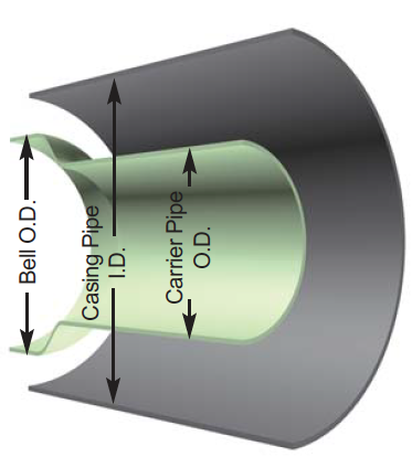
Ranger II Casing Spacer by GPT

- Ranger II Casing Isolators are designed primarily for smaller diameter steel or polyethylene carrier pipes.
-
Description
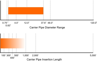
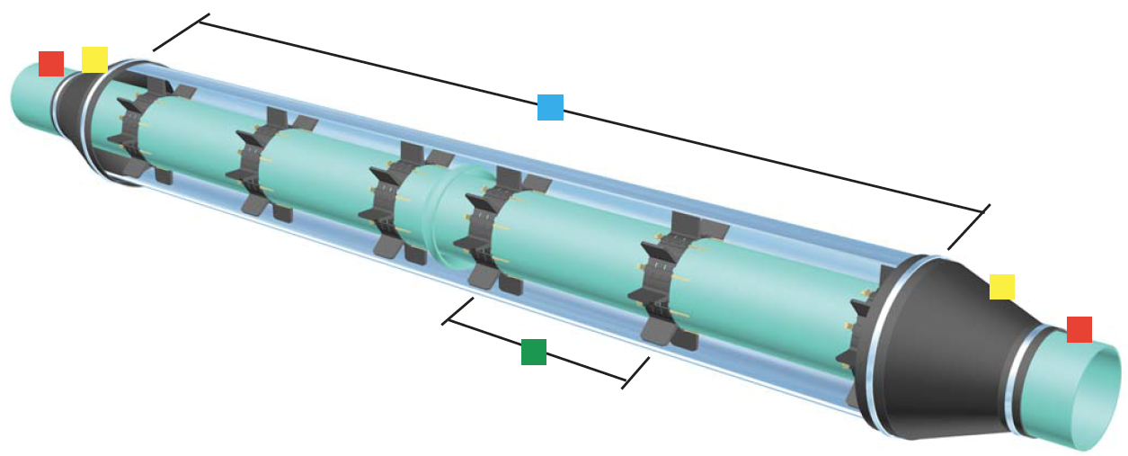
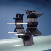
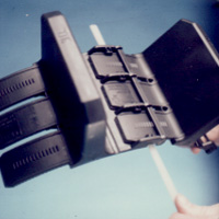
The Ranger II is an all non-metallic casing isolator/spacer system that uses molded segments to encircle the carrier pipe. Each segment includes at least one molded-in runner and one slide lock. Customer's may choose from any one of five different size bands to allow correct sizing for carrier pipe O.D. ranges from 0.83" (21.1mm) up to 37.60" (95.5cm) in diameter.
Once sized, the segments are placed around the carrier pipe and cinched together via non-metallic slide locks. Installation is quick and easy while only a small inventory of segments may be used to accommodate a large variety of pipe styles, types and diameters.
Targeted Use - Water

For carrier pipe insertion lengths up to 400 feet.* (121.9M)


Ranger II spacers should not be used on concrete carrier pipe. Engineered equal to 304 Stainless Steel Metallic Casing Spacers. Excellent for the Stocking Distributor.
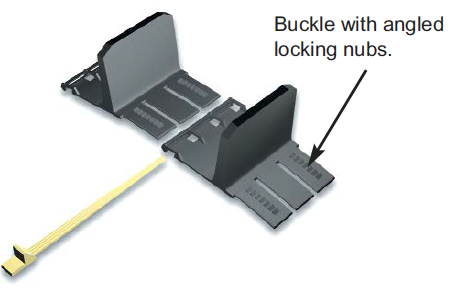
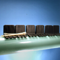
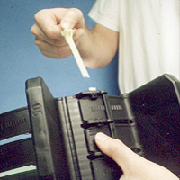
Separate segments are connectedby inserting the buckles into slots on the adjacent segment. Slot accepts Slide- Lock. Arrow molded on segment indicates correct insertion direction.
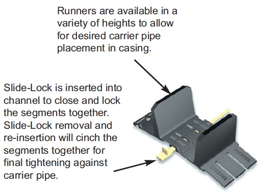
Slide-Lock is used to tension the segments together after installation on pipe. Channels face up during insertion while the correct size Slide-Lock (micro, mini, midi, medi, maxi) is molded on the flat (bottom) side.
Features
- All non-metallic. No nuts, bolts, washers or any other metal parts to corrode or degrade over time.
- Designed for carrier pipe diameters from 0.83” (21mm) to 37.60” (955mm) in diameter.
- Segmented pieces - small inventory may be used to accommodate a large variety of pipe styles, types and diameters. No extra trips from job site to warehouse for additional parts.
- Easy assembly. Simply slide the segments together and cinch tight with the patented Slide-Lock connecting system.
- Wide variety of runner heights to allow numerous options for pipe positioning within the casing.
- Runner variations may be used to adjust for grade.
- Will accommodate small conduit attachment for communications or electrical cable.
- Medi and Maxi segments, 2 molded runners per segment.
- Segment band and runners molded as one piece.
- Manufactured from UV resistant polypropylene.
- High impact strength, 1.5 ft. lbs./inch (0.8 joules/cm)
- Excellent compressive strength, 3,000 psi (211 kg/square cm)
- 800 Volts/Mil. Dielectric Strength.
- Wide temperature range, -22. to +212. F. (-30. to +100. C.)
- Eliminates sand or grout fill.
- No special tools required for installation.
- Low coefficient of friction for ease of installation.
-
Typical Specifications for Ranger II Casing Spacers
Non-metallic Casing Spacer & End Seal Specification for Carrier Pipe up to 37.60 O.D.
A. Casing Spacers
Upon completion of the installation of the steel pipe encasement, the contractor shall furnish and install a Ranger II boltless casing spacer on the carrier pipe as described below. Casing spacers shall be spaced a maximum of eight (8) feet apart along the length of the carrier pipe with one casing spacer within two (2) feet of each side of a pipe joint and the rest evenly spaced. Wood skids are not an acceptable method of supporting the carrier pipe.1. Casing spacers shall be all non-metallic (polypropylene), molded in segments for field assembly without any special tools. Spacer segments shall be secured around carrier pipe by insertion of a Slide-Lock. The casing spacer polymer shall contain ultraviolet inhibitors and shall have a minimum compressive strength of 3,000 psi, an 800 Volts/mil dielectric strength and impact strength of 1.5 ft-lbs./inch. Each casing spacer shall have full length, integrally molded skids extending beyond the bell or mechanical joint of the carrier pipe.
2. The casing spacers shall be the PSI Ranger II Casing Spacers as manufactured by Pipeline Seal and Insulator, Inc., Houston, Texas.
3. Spacers shall be at least as wide as listed below.
Carrier Pipe Diameter
Inches (mm)Ranger II
ModelLength
Inches (mm)0.83 to 3.07"
(21 to 78)Micro
2.13" (54)
2.48 to 5.51"
(63 to 140)Mini
3.15" (80)
5.51 to 16.65"
(140 to 423)Midi
5.12" (130)
16.77 to 25.98"
(426 to 660)Medi
6.87" (174)
25.98 to 37.60"
(660 to 955)Maxi
8.86" (225)
B. End Seals
After insertion of the carrier pipe into the casing, the ends of the casing shall be closed by installing 1/8" thick synthetic rubber end seals equal to the PSI Model "C" end seal as manufactured by Pipeline Seal and Insulator, Inc., Houston, Texas.ISO 9001:2000 Registration
Each casing spacer and end seal shall be manufactured at a facility that has a Registered ISO 9001:2000 Quality Management System. Copy of current ISO 9001:2000 Registration shall be provided with material submittal.Material Specifications for Ranger II Casing Spacers
SPECIFICATION
ASTM TEST
VALUE
Band/Runner Segments
Injection molded virgin polypropylene
Tensile Strength
D790
8,100 - 9,000 psi
Compressive Strength
D695
3,000 psi
(211 kg/cm²)Water Absorption
D570
0.1%
Temperature
-22 to +212° F.
(-30 to +100° C.)Impact Strength
D256
1.5 ft. lb./in.
0.8 joules/cmDielectric Strength
D149
800 volts/mil. min.
Color
Black
Liner
None
Hardware
Non-metallic - Slide Locks - No Metallic PartsRanger II Non-metallic Casing Spacers
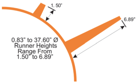
- Ranger II runners are molded as an integral part of each segment.
- Runner height range from 1.50” (38.1mm) to 6.89” (175.0mm).
- Runners may be placed asymmetrically around spacer.
- Runner/Segment widths for Ranger II spacers is 2.13” (54.1mm) through 8.86” (225.04mm).
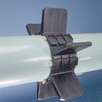
Ranger II Non-metallic Casing Spacers
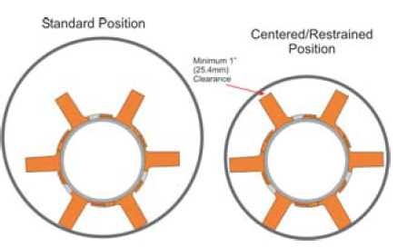
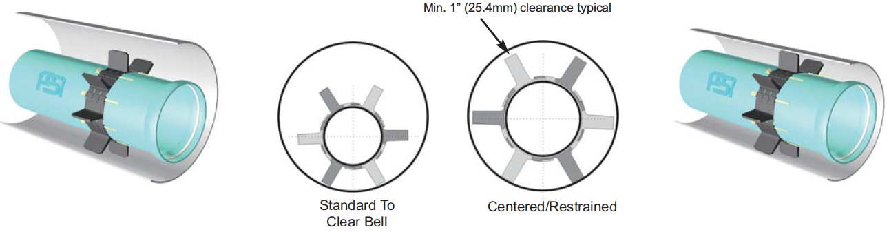
- Multiple positions within casing possible.
- Different height runner segments may be mixed around carrier pipe.
- Runner height may be asymmetrical around carrier pipe.
- Positioning options include: standard (clear bell), centered, centered-restrained and non-centered-restrained
-
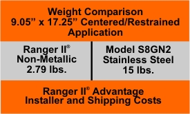
Weight and Spacing Guidelines
Ranger II Casing Spacers Skid Height Spacing: (Maximum Distance Between Casing Spacer.)
Skid Height 1.50” (38mm) to 1.97” (50mm) 8’ (Feet)
Skid Height 2.56” (65mm) to 3.54” (90mm) 6’ (Feet)
Skid Height 3.94” (100mm) and up 5’ (Feet)Installed On Various Pipe Types, Such As:
PVC Water, PVC Sewer, HDPE Steel, Ductile Iron...etc.
Ranger II Casing Spacers Skid Height Max Load Per Spacer:
MICRO MINI MIDI MEDI MAXI Skid Height 1.50” (38mm) to 1.97” (50mm)
175 lb. 500 lb. 1,250 lb. 3,3000 lb. 5,000 lb. Skid Height 2.56” (65mm) to 2.95” (75mm)
135 lb. 400 lb. 1,000 lb. 2,600 lb. 4,000 lb. Skid Height 3.54” (90mm) to 3.94” (100mm)
120 lb. 350 lb. 875 lb. 2,300 lb. 3,500 lb. Skid Height 4.92” (125mm) to 5.91” (150mm)
250 lb. 625 lb. 1,650 lb. 2,500 lb. Skid Height 6.89” (175mm)
550 lb. 1,400 lb. 2,300 lb. 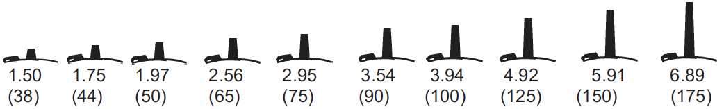
Ranger II - Micro for 0.83 to 3.07” (21 to 78mm) Diameter Carrier Pipe Band Width = 2.13” (54mm)
Carrier Pipe O.D. Range Inches (mm) No. of Segments Runner Height Options Inches (mm) 0.83 to 1.14 (21 to 29) 3 Verify that Slide-Locks match segment size: Make sure (Mini) matches name molded
on the bottom of the Slide-Lock. Note: Micro & Mini segments both use the Mini Slide-Lock.1.14 to 1.54 (29 to 39) 4 1.54 to 1.85 (39 to 47) 5 1.85 to 2.24 (47 to 57) 6 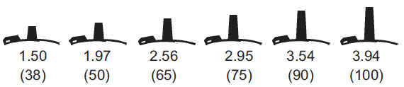
2.24 to 2.48 (57 to 63) 7 2.48 to 3.07 (63 to 78) 8 Ranger II - Mini for 2.48 to 5.51” (63 to 140mm) Diameter Carrier Pipe Band Width = 3.15” (80mm)
Carrier Pipe O.D. Range Inches (mm) No. of Segments Runner Height Options Inches (mm) 2.48 to 3.07 (63 to 78) 4 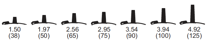
3.7 to 3.86 (78 to 98) 5 3.86 to 4.49 (98 to 114) 6 4.49 to 5.51 (114 to 140) 7 Verify that Slide-Locks match segment size by checking to ensure the segment name (Mini) matches the name molded on bottom of the Slide-Lock. Note: Micro & Mini segments both use the Mini Slide-Lock. Ranger II - Midi for 5.51 to 16.65” (140 to 423mm) Diameter Carrier Pipe Band Width = 5.12” (130mm)
Carrier Pipe O.D. Range Inches (mm) No. of
SegmentsRunner Height Options Inches (mm) 5.51 to 6.89 (140 to 175) 4 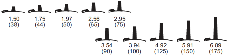
6.89 to 8.70 (175 to 221) 5 8.70 to 10.31 (221 to 262) 6 10.31 to 12.87 (262 to 327) 7 12.87 to 14.41 (327 to 366) 8 14.41 to 16.65 (366 to 423) 10 Verify that Slide-Locks match segment size by checking to ensure the segment name (Midi) matches the name molded on the bottom of the Slide-Lock Ranger II - Medi for 16.77 to 25.98” (426 to 660mm) Diameter Carrier Pipe Band Width = 6.87” (174 mm)
Carrier Pipe O.D. Range Inches (mm) No. of
SegmentsRunner Height Options Inches (mm) 16.77 to 21.22 (426 to 539) 4 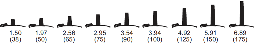
21.22 to 25.98 (539 to 660) 5 Verify that Slide-Locks match segment size by checking to ensure the segment name (Maxi) matches the name molded on the bottom of the Slide- Lock. Note: Medi & Maxi segments both use the Maxi Slide-Lock. Ranger II - Maxi for 25.98 to 37.60” (660 to 955mm) Diameter Carrier Pipe Band Width = 8.86” (225mm)
Carrier Pipe O.D. Range Inches (mm) No. of
SegmentsRunner Height Options Inches (mm) 25.98 to 30.79 (660 to 728) 6 30.79 to 37.60 (782 to 955) 7 Verify that Slide-Locks match segment size by checking to ensure the segment name (Maxi) matches the name molded on the bottom of the Slide- Lock. Note: Medi & Maxi segments both use the Maxi Slide-Lock.
-
Installation Instructions for Ranger II Casing Spacers
Always Wear Appropriate Safety Equipment and Follow All Your Company Regulations! Basic Installation Procedure
Precautions
Always Use Appropriate Protective Safety Wear and Glasses!- Always wear protective safety glasses, especially in low temperatures.
- Keep Ranger II segments and slide-locks in a warm environment while awaiting installation in colder climates.
- Under hot installation conditions, allow the product to age a couple of hours at ambient temperature prior to assembly.

1. Check to make sure you have all segments and Slide-Locks as recommended by ordering procedure.
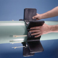
2. Take the segments and align the buckles. Insert the buckles 1/4 of the way into the slots.
3. Locate directional arrow on segment and insert Slide-Lock until the tip exits the end of the segment.
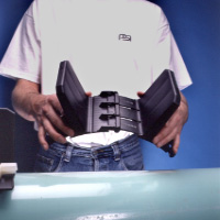
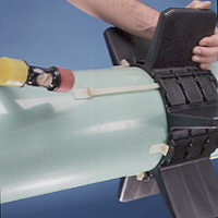
4. Continue the process from the previous step until all segments are put together. You are now ready to wrap the Ranger II around the pipe.NOTE: In tight installation areas, you might need to break the belt into two parts and then wrap the Ranger II around the pipe.
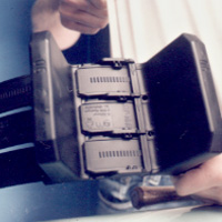
5. Align the buckles and lock into place. Take the final Slide-Lock and slide completely into place.
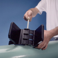
6. Insert all Slide-Locks as far as possible by hand. Complete tightening by lightly tapping each Slide-Lock with a light rubber headed hammer, while holding the Slide-Lock against the pipe.
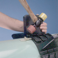
7A. To tighten Ranger II securely to carrier pipe, back Slide-Lock completely out of the slot. If needed, push segments together by hand.
7B. Re-insert Slide-Locks completely into segment by lightly tapping Slide-Lock back into position while holding the Slide-Lock against pipe.
7. Continue steps 7A and 7B until Ranger II is secure against carrier pipe and unable to move.
Trouble Shooting Installation Procedure
Broken Slide Lock:
A) If a Slide-Lock should break during installation, remove and replace with a new Slide-Lock.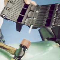
B) Remove Slide-Lock by backing it out, do not pull it through to remove the broken piece. Tap broken piece back out.
C) Take a Slide-Lock and insert in the opposite direction of the arrows. Push until you can grab the broken piece and remove.
Slide Lock will not insert completely:
D) If the Slide-Lock does not completely lock into place the following may have occurred. Two or more segments may have engaged completely. To rectify, back Slide-Lock out and readjust segments by pulling them apart by hand. Reinsert Slide-Lock and adjust tightness of the spacer with another segment.Size your Installation Application
All Ranger II. Casing Spacers require more than one segment to complete a spacer. In addition, all Ranger II Casing Spacers are available with a number of different runner height options which are used to guarantee clearance of the mechanical joint, provide for options in carrier pipe positioning within the casing or to compensate for grade elevation adjustments. Following are examples on how to size Ranger II Casing Spacers for various applications. Detailed Ranger II casing spacers weight & spacing guidelines on page 11. For exact centering and adjusting for grade elevation changes contact PSI.
Examples
Centered & Restrained with Equal Length Runners
20” Ductile Iron pipe (21.60” O.D. barrel & 28.63” O.D. bell) inside a 36” casing with a 0.375” wall thickness.
A. Find carrier pipe O.D. (21.60”) from adjacent chart and choose the proper size and number of segments. One spacer would require 5 - Medi segments.
B. Determine maximum runner height with equal length runners.
Case I.D. 35.25" Less Carrier Pipe O.D. -21.60"
13.65"Less Space Allowance -1.00"
12.65"
Divide this number (12.65”) by 2 to obtain the total maximum runner height = 6.325”C. Choose a runner height of this value or less.
Solution: Use 5 - Medi (150) segments with runner heights of 5.91”.Note: This combination will restrain the pipe from flotation within the casing pipe by allowing only about 1.8” of clearance between the top runners and the casing I.D. This will center the carrier pipe within approximately 0.9” of exact center.
To Clear the Bell (suggested minimum clearance is at least 0.8” (0.4” on both sides)
20” Ductile Iron pipe (21.60” O.D. barrel & 28.63” O.D. bell) inside a 36” casing with a 0.375” wall thickness.
Determine runner height.
(Clear Bell)Bell O.D. 28.63" Add 0.8" Clearance +0.80"
29.43"Less Barrel O.D. -21.60"
7.83"
Divide this number (7.83”) by 2 to obtain the minimum runner height to clear the bell = 3.92”
Choose a runner height between 3.92” and the maximum allowable runner height (6.32”) determined in the above example.Solution: Use 5 - Medi (100) segments with runner heights of 3.94”.
-


