DCVG Coating Holiday Survey Set by DCVG Ltd.
Description
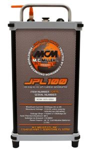
Equipment can be purchased as a Full set or as a Basic Set. All DC Voltage Gradient Equipment Sets come with spares and is manufactured in UK to military specifications. A FULL set comes complete with everything except a DC power source needed to survey a buried pipeline. The equipment which is a direct descendant from the original work carried out in Australia is packed into protective carry cases and has two main components, the Interrupter and the Survey Meter. During manufacture maximum emphasis has been placed on simplicity, quality and robustness of construction with the equipment kept as flexible as possible to use. Although the equipment comes with an instruction booklet, a very comprehensive training course is available to ensure operators know how to gather data and to use and interpret results in order to gain maximum benefit from the technology transfer process. The Basic Set consist of the same quality components but the mimium components required to do DCVG Surveys. There are no carry cases or spares in a BASIC set.
For pipelines with multiple rectifiers, we recomment the purchase of Satelllite Controlled Synchronous Interrupters so all rectifers are switcing ON/OFF at same time.
Features
Full DCVG Set Components List:
- 1x DCVG Survey T/R Interrupter
(Non Synchronisable)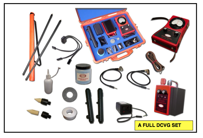
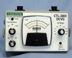
- 1x DCVG Survey Meter
- 2x Probe Handles (Bias)
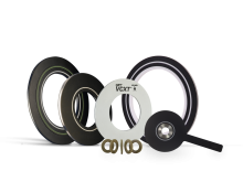
- 2x Copper Sulphate Reference Probes
- 1x Right Hand Connection Leads
- 1x Left Hand Connection Leads
- 2x Reference Probe Tip Holders
- 4x Probe Tip Washers
- 4x Wooden Probe Tips
- 1x PTFE Sealing Tape
- 1x 120/240 Volt Battery Charger
- 1x Battery Charger Connection Lead
- 1x Probe Filler Bottle
- 1x Copper Sulphate Crystals (JAR)
- 1x Equipment Carry Case
- 1x Probe Carry Case
- 1x DCVG Instruction Manual
- 1x DCVG Survey T/R Interrupter (Non Synchronisable)
- 1x DCVG Survey Meter
- 1x Bias Probe Handle
- 1x Plain Probe Handle
- 2x Copper Sulphate Reference Probes
- 1x Right Hand Connection Lead
- 1x Left Hand Connection Lead
- 2x Reference Probe Tip Holders
- 2x Probe Tip Washers
- 4x Wooden Probe Tips
- 1x PTFE Sealing Tape
- 1x 120/240 Volt Battery Charger
- 1x Battery Charger Connection Lead
- 1x Users Manual
Contents
|
Item Number |
DCVG SET – ITEM |
Full DCVG Set Quantity |
Basic DCVG Set Quantity |
|
1 |
DCVG Survey Meter |
1 |
1 |
|
2 |
50 amp Satellite Interrupter or 125 amp Satellite Interrupter |
1 |
1 |
|
3 |
Interrupter Satellite Aerial |
1 |
1 |
|
4 |
Power Cable to External 12 Volt Battery |
1 |
1 |
|
5 |
Probe Bias Handle |
2 |
2 |
|
6 |
120/240 Volt Battery Charger |
1 |
1 |
|
7 |
3-Way Battery Charger Adaptor Lead |
1 |
1 |
|
8 |
Right Hand Connection Lead |
1 |
1 |
|
9 |
Left Hand Connection Lead |
1 |
1 |
|
10 |
Jar of Copper Sulphate |
1 |
None |
|
11 |
Probe Filler Bottle |
1 |
None |
|
12 |
Probe Tip |
4 |
4 |
|
13 |
Probe Tip Washer |
4 |
4 |
|
14 |
Probe Tip Holder |
2 |
2 |
|
15 |
PTFE Sealing Tape |
1 |
1 |
|
16 |
Reference Probes - DCVG |
2 |
2 |
|
17 |
Reference Probe Carry Case |
1 |
None |
|
18 |
Equipment Carry Case with Blue Insert |
1 |
None |
|
19 |
DCVG User Manual |
1 |
1 |
|
20 |
50 or 125 Satellite Interrupter User Manual |
1 |
1 |
|
21 |
Packing List in Documents Folder |
1 |
1 |
|
22 |
Certificate of Origin in Documents Folder |
1 |
1 |
|
23 |
Certificate of Calibration & Equipment Test in Documents Folder |
1 |
1 |
|
24 |
Guarantee in Documents Folder |
1 |
1 |
|
25 |
Certificate of Conformity & Traceability in Documents Folder |
1 |
1 |
|
26 |
Certificate of Quality & Quantity in Documents Folder |
1 |
1 |
History
Principle of the DC Voltage Gradient Technique
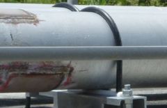
In Cathodic Protection when current flows through the resistive soil to the bare steel exposed at faults in the protective coating, a voltage gradient is generated in the soil. The larger the fault the greater the current flow and hence voltage gradient and this is utilised in the technique to prioritise faults for repair. The voltage gradient is observed by measuring the out of balance between two copper sulphate electrodes utilising a specially designed milli-voltmeter. When the two electrodes are placed 1.5 meters apart on the soil in the voltage gradient from a coating fault, one electrode adopts a more positive potential than the other which allows the direction of current flow to be established and fault to be located. To simplify the fault location interpretation, the applied CP is separated from all other DC influences such as Tellurics, DC Traction etc, by pulsing the local CP ON and OFF in an unsymmetrical fashion. The pulsing DC can be from the pipeline CP system itself, or from an independent source such as a portable DC generator or batteries utilising a temporary groundbed and impressed on top of a pipelines existing CP system.
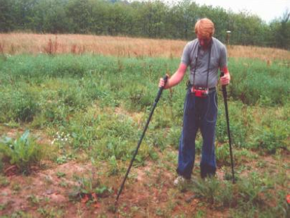
In surveying a pipeline, the operator walks the pipeline route testing for a pulsing voltage gradient at regular intervals. As a fault is approached, the surveyor will observe the milli-voltmeter needle begin to respond to the pulse, pointing in the direction of current flow
that is towards the fault.
When the fault is passed the needle direction completely reverses and slowly decreases as the surveyor moves away from the fault. By retracing to the fault, a position of the electrodes can be found where the needle shows no deflection in either direction (a null). The fault is then sited midway between the two electrodes. This procedure isthen repeated at right angles to thefirst set of observations, and where the two midway positions cross is the epicentre of the voltage gradient. This is usually directly above the coating fault.
In order to determine various characteristics about a fault, such as severity, shape, corrosion behaviour, etc, various electrical measurements around the epicentre and from epicentre to earth are made for interpretation.
The beauty of the DCVG technique is that it utilises the existing pipeline CP system at its normal setting wherever possible and hence results reflect the intimate interaction between the protective coating degradation and the effectiveness of CP at individual coating faults. This is very powerful information in the fight against corrosion. No AC or Electromagnetic Technique offers such a direct study capability.
The DCVG Technique can be applied in City Streets, Process Plant and Refineries, across Rivers and Estuaries, Swamps, Parallel Pipeline systems, to Gas, Oil, Chemical and Water Pipelines. Also DCVG can be used to evaluate the protective coating on Telephone and Power Cables.
ECDA Data Analysis
Not every coating fault or metal loss location requires repair. In practice, for most pipelines, 99+% of all coating faults have no metal loss but there is the potential for metal loss if there is a coating fault with weak CP in low resistivity soil. While the repair of critical metal loss is important, most pipelines are rehabilitated on the basis of the need to improve the protective coating in order to make the CP more effective. Remember, in line inspection tools detect the symptom of the problem. DCVG equipment, when combined with potential measurements, detect the real cause of the problem that leads to metal loss, which is a breakdown in corrosion control through coating failure and an inadequate CP system.
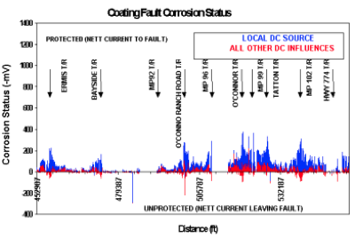
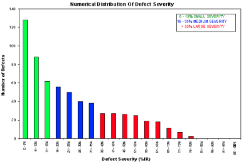
There is never enough money to repair all coating faults. Detailed analysis of data is required to identify large, current consuming coating faults, particularly those in low soil resistivity areas. These coating faults should be repaired releasing CP current that then becomes available to improve protection of those faults not identified for repair.
Properties
What Are The Properties Of A Coating Fault That We Should Measure?
The collection and analysis of the correct information is important to make your Pipeline Integrity Activities both cost and technically effective. Identified in this table in order of priority are the properties of coating faults that need to be measured to provide data for the best subsequent analysis.
Properties of a Coating Fault Required for Proper Fault Analysis
|
PRIORITY |
PROPERTY |
TECHNIQUE USED |
|
1 |
Fault Cathodic Current |
DCVG |
|
2 |
Fault Anodic Current |
DCVG |
|
3 |
Net Current Flow To/From Fault |
DCVG |
|
4 |
Soil Resistivity |
EM |
|
5 |
CIPS OFF potential |
CIPS |
|
6 |
CIPS ON Potential |
CIPS |
|
7 |
DC Interference |
DCVG & CIPS |
|
8 |
AC Interference |
Voltmeter |
|
9 |
Disbondment |
Visual/DCVG/ Coating Type |
|
10 |
Soil pH |
pH Meter |
|
11 |
Type of Soil |
Visual |
|
12 |
Vegetation / Roots |
Visual |
|
13 |
Fault Severity |
DCVG |
|
14 |
Fault Size |
Visual on Excavation |
|
15 |
Location |
DCVG/GPS |
|
16 |
Proximity to Another Fault |
DCVG/GPS |
|
17 |
Overall Density of Faults |
DCVG/GPS |
|
18 |
Type of Coating |
Records |
|
19 |
Field Joint Coating |
Records |
|
20 |
Age of Coating |
Records |
EM = Electromagnetic Soil Resistivity Measurement.
DCVG = Analogue DC Voltage Gradient Technique. This table does not apply to so called combined digital DCVG/CIPS which is really just lateral CIPS and is a sham technique.
CIPS = Close Interval Potential Survey Technique also known as CIS in North America.
GPS is sub-metre GPS Location and Distance measurement equipment, eg. Trimble Pro XRT