
EXPERT TIP #26: USE AND MISUSE OF AN OHMMETER
Purpose of an Ohmmeter
The modern portable digital multimeter (DMM) is an indispensable tool with many functions and
features. Typically, a DMM is used to measure AC and DC voltages and currents. In addition to these
features, they also include an Ω (OHM) function to measure the electrical resistance between two
points.
Under the right conditions, the ohmmeter can accurately measure from 1 ohm to as much as 60
megohm (60 million ohms). The key phrase here is “under the right conditions.” The DMM operator
needs to understand how the meter functions and the conditions that can yield errors in measurement.
All ohmmeters will apply a regulated current (typically one milliamp) through the test leads across the
circuit being measured. The applied current will result in a voltage drop across the component being
tested. The meter utilizes an algorithm calculation that uses Ohm’s Law (R=E/I) to calculate and display
the resistance in ohms, kilohms, or megohms.
Ohmmeter Guidelines
Using an ohmmeter is straightforward. Yet, it is important to follow some basic guidelines to ensure
accurate measurements and safety. Following are guidelines for using an ohmmeter:
1. Safety First: Always ensure that the circuit or device you intend to test is disconnected from any
power source, which includes unplugging the power cords or switching off circuit breakers. This
prevents the risk of electric shock and damage to the ohmmeter. Once the device is not energized,
testing can proceed.
2. Clean Contacts: Ensure that the test leads (wires with probes) and items to be tested are clean and
free from any debris or oxidation. Dirty contacts can affect the accuracy of the resistance
measurement.
3. Disconnect Components: If testing a specific component within an electrical circuit, make sure the
component is disconnected from the electrical circuit. This prevents parallel paths from affecting the
measurement.
4. No Voltage: Don't measure resistance in a circuit where voltage is present. Voltage can interfere
with the ohmmeter's reading and potentially damage the device.
5. Switch the DMM Dial to the Ohm (Ω) Function: Ensure the correct meter function has been
selected.
6. Test the Meter: Short the two test leads together to ensure the meter and leads function correctly.
The DMM reading should be stable and repeatable. It is common for test lead cables to have
between 0.3 and 1.0 ohms. Therefore, when measuring low-resistance devices, such as a fuse or a
length of wire, remember that the resistance of the meter test leads will be added to the measuring
circuit.
7. Hold the DMM Probes Properly: Hold the test lead probes with their insulated handles when
measuring resistance. Avoid touching the metal parts of the test lead probes, as this can introduce
additional resistance to the measurement and be very misleading when measuring high-resistance
devices.
8. Good Contact: Press the probes firmly against the test locations to ensure the metal probes make
good electrical contact with the points being measured.
Testing Dielectric Fittings with an Ohmmeter
In the cathodic protection (CP) industry, technicians often use an ohmmeter to determine the condition
of a dielectric insulating flange, union, or similar fitting. While it may seem straightforward to use the
ohmmeter, it will likely provide unreliable results. This is why the following should be considered:
When testing an installed dielectric fitting, i.e., connected to a pipeline on both sides of the dielectric
fitting, even if the CP system is in the OFF condition, there will likely be a voltage differential across the
two sides of the dielectric fitting. This will violate the above guidelines #3 & #4. This voltage will be
applied to the internal calibration circuitry of the DMM and will result in an inaccurate resistance
measurement. Therefore, this measured value is only “interesting information” due to its inaccurate
value. If the test lead polarity is reversed and the test repeated, an entirely different resistance value
would appear. The good news is that if the DMM reads some value of resistance, it would mean that the
fitting is NOT shorted, as a shorted dielectric fitting would read close to zero ohms.
In the case of a dielectric isolating flange, an electrically shorted or resistive fitting can be caused by
several different problems. Obviously, if the gasket has failed or “bridged” internally, the quality of
electrical isolation will be compromised. In the case of dielectric insulating flange kits, if the isolation
between the threaded stud and the flange is compromised, the flange may be shorted or not affect the
isolation.
To provide electrical isolation of a flanged pipe fitting, the flange gasket must be made of an electrically
isolating material, and the threaded studs of the fitting must be electrically isolated from at least one of
the flange faces.
There are two configurations of flange isolation kits:
1. Single Washer and Sleeve - FIGURE A: With this configuration, the individual studs will be
electrically isolated from one of the two flanges.
2. Double Washer and Sleeve - FIGURE B: All the threaded studs are electrically isolated from both
flanges in this configuration. This is by far the most popular configuration.
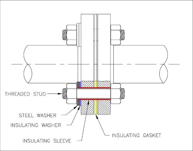
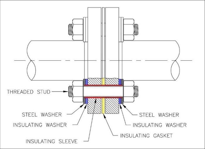
FIGURE A FIGURE B
An ohmmeter can properly test electrical isolation between the flange and the threaded studs.
When testing FIGURE A, assuming the gasket provides electrical isolation, the resistance between the
stud and flange 1 will indicate some resistance. However, this again violates guidelines 3 & 4, which is
not a good idea. Testing between the stud and flange 2 will indicate zero resistance.
When testing FIGURE B, assuming the gasket provides good electrical isolation, the resistance between
the stud and either flange should be high.
If it is possible to test a dielectric insulating fitting before installation, you should do so with the
dielectric fitting (isolating union, assembled flange, monolithic isolating joint, or similar) on a nonconductive surface, such as wood. Because there will be no voltage differential between the two sides
of the fitting, using an ohmmeter to test the effectiveness of the dielectric fitting is a proper test.


