Most Cathodic Protection (CP) technicians understand the purpose and operating features of CP rectifiers. However, when the CP system goes down, troubleshooting a CP rectifier may require some help.
The following provides a basic understanding of the function of the CP rectifier and some basic troubleshooting tests that can identify many of the common rectifier problems.
What is a CP rectifier?
A CP Rectifier (also referred to as a CP power supply, Transformer Rectifier or TR) works by converting alternating current (AC) from the power source into direct current (DC), which is necessary to protect metal structures from corrosion. Here is how a CP rectifier works:
POWER SOURCE
AC Input: The rectifier unit receives AC power from an external power source, normally the electrical grid. Since input voltage can vary, it is important that the rectifier can accept the available input voltage.
TRANSFORMATION
Transformer: The AC voltage is passed through a transformer. The transformer’s primary function is to step down the input AC voltage to a suitable level required for the cathodic protection system. The transformer also electrically isolates the power source from the output circuitry to ensure proper isolation of the protected structure.
RECTIFICATION
Rectifier Stack: The transformed AC voltage is then fed into the rectifier “stack.” The stack consists of diodes (semiconductor devices) that allow current to flow in only one direction. This process converts the AC voltage, which oscillates between positive and negative, into a “unidirectional cycling DC voltage” with only one polarity.
Remember that the CP rectifier is an adjustable DC power supply or voltage source. The resulting DC current or amperage output is a function of the anode-to-structure circuit load resistance.
Note: If the rectifier you need to troubleshoot is any type other than a basic CP rectifier or transformer rectifier described above, such as an electronic constant potential, constant current or switch-mode technology, the troubleshooting methods below may not apply. Always refer to the manufacturer’s operating manual for specific instructions and safety guidelines for your particular rectifier model.
Basic Troubleshooting Steps
SAFETY FIRST! Some CP rectifiers contain high voltages (up to 680 volts). If you are not trained and qualified to work on this type of equipment, STOP and get help from a qualified electrician.
Potential Problem #1: The CP rectifier is operational and indicates DC voltage output but zero
DC current output.
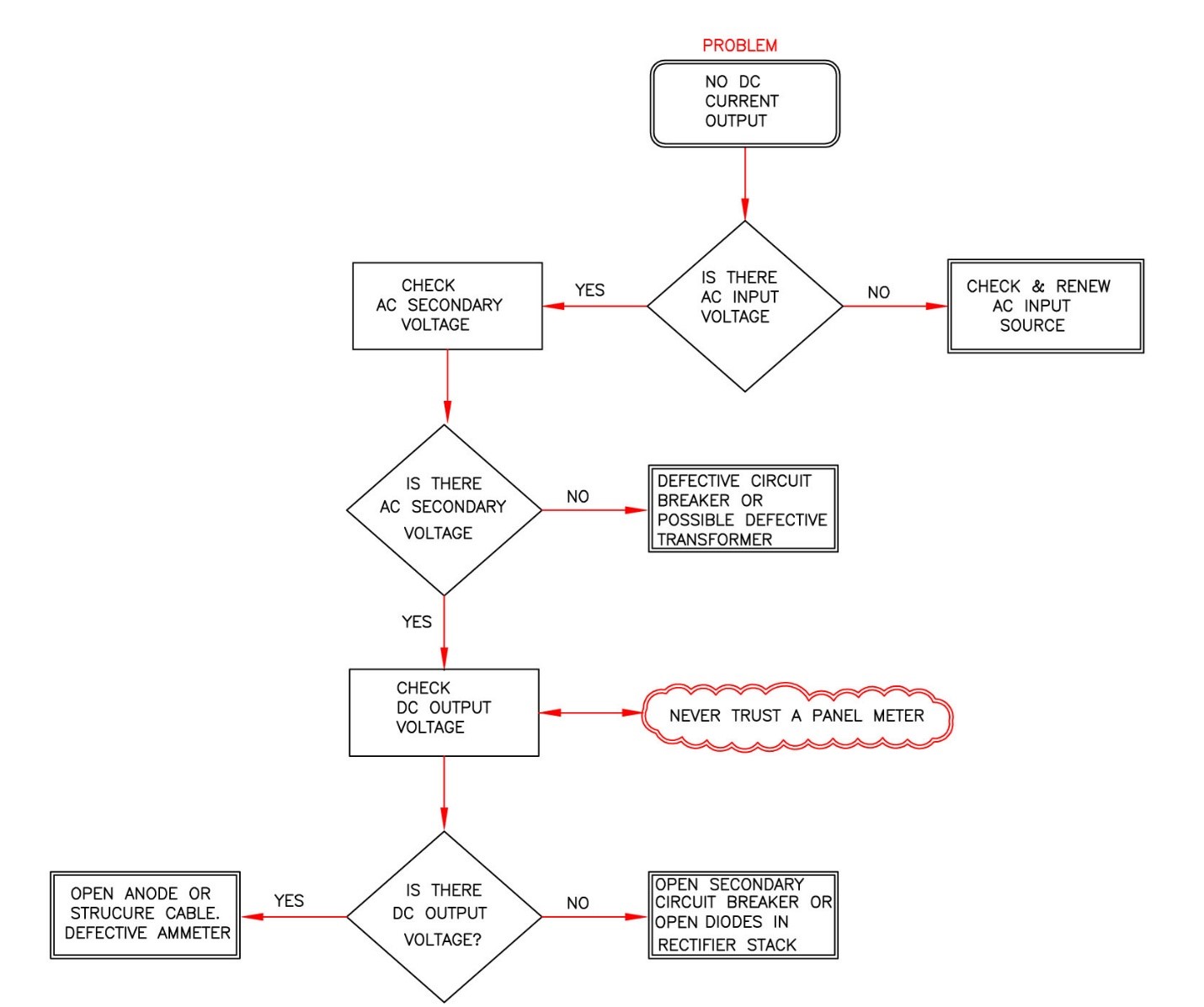
- Using a portable digital meter, confirm that there is DC output voltage. Never trust the rectifier panel voltmeter in this case. The meter may indicate voltage, but the indicating needle could be stuck.
- Once confirmed that the CP rectifier is providing DC voltage, go to Step #3
- To confirm that the ammeter is functional, check the millivolt (mV) drop across the provided front panel meter shunt. If there is a measurable mV drop, then the ammeter is faulty.
- Under the above conditions, it can be concluded that the CP rectifier is working properly but has a defective ammeter.
- If the voltage is confirmed and zero current is confirmed, it is likely that that rectifier is operational, but there is an open circuit (broken cable) in the anode and/or the structure cable.
IMPORTANT: When a rectifier has a confirmed voltage output but zero current output, there is a very high probability that the basic CP rectifier unit is operational. This is likely the most common misdiagnosed rectifier problem.
Potential Problem #2: The CP rectifier indicates zero voltage and zero current output.
- Check the AC input voltage at the AC input terminal block with the rectifier breaker switched to the “ON” position. Caution: The AC voltage can be as high as 680 VAC.
- If the measured voltage is zero or lower than it should be, contact the site electrician for further investigation.
- If the AC input voltage is okay or as expected, check to ensure that the main panel circuit breaker is “ON” and has not tripped.
- If the main AC input breaker is confirmed ON, next check the AC voltage between the front panel “Coarse” and “Fine” voltage adjustment taps. If the AC voltage is zero, the problem is likely a defective main circuit breaker or an open winding in the transformer.
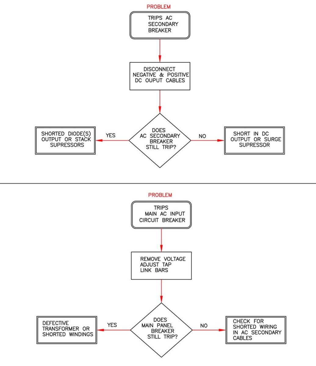
- If AC voltage is OK as measured between voltage adjust taps, check if the AC secondary circuit breaker or fuse is operational. If the AC secondary breaker has tripped or the fuse is blown, the problem is likely a shorted rectifier stack and/or shorted AC or DC surge suppressors on the stack or a short on the DC output circuit.
- Switch “OFF” the rectifier main breaker and disconnect the anode and structure cables. With the cables disconnected, switch “ON” the rectifier main circuit breaker and confirm that the AC secondary breaker (or fuse) is operational. If the rectifier is now functioning with confirmed DC output voltage (and zero current), this indicates that it is operational and there is a short in the DC output circuit.
Potential Problem #3: The CP rectifier unit is operational, yet the rectifier output indicates half voltage and half current compared to previous inspections.
- Check the DC output frequency using a digital multimeter set to measure DC voltage.
- While measuring the DC voltage, press the “Hz” button on the multimeter. A properly operating CP rectifier should read 120 Hz. If you only read 60 Hz, there are one or more open or malfunctioning diodes in the rectifier stack.
Note: Measuring a frequency on the DC function of the DMM may seem erroneous. Remember, the actual output of a typical CP rectifier is NOT pure DC but a “unidirectional cycling voltage.” Therefore, it has an AC component. The DMM on the “Hz” function can detect this AC component and measure the frequency. A normal reading for a single-phase rectifier is 120 Hz. A measurement of 60 Hz indicates that one or more of the diodes are open and the rectifier is operating in a half-wave function. This means that the rectifier is providing half the voltage and current as compared to the output of a properly functioning rectifier.
Important! If the rectifier is equipped with a filter choke, your meter may not be able to detect any frequency as the filter reduces or eliminates the AC component.
Refer to the flow chart below for additional troubleshooting methods. Some of these troubleshooting techniques will require a qualified electrician to safely complete the testing.
Additional tasks or checks that should be conducted
VISUAL INSPECTION
- Physical Damage: Look for signs of damage to the rectifier enclosure, as this can also indicate physical internal damage. Inspect the CP rectifier for broken wires, burned components, or loose connections.
- Inspect the Environment: Ensure the CP rectifier’s internal components are clean and properly ventilated. Dust and debris on the internal components can cause problems such as overheating.
- Inspect Components: Ensure all tap bars and fuses are intact, clean and tight. Verify that the circuit breakers have not tripped. Replace any blown fuses and reset any tripped breakers.
GROUNDING AND BONDING
- Verify Grounding: Ensure that the rectifier is properly grounded, as poor electrical ground can cause a shock hazard.
- Check Electrical Connections: Inspect for loose, corroded, or damaged connections. All connections should be intact and corrosion-free
When to Call for Assistance
We all have technical limitations, so if you find an issue or condition you do not understand, you should seek help. Consider seeking help if you encounter complex problems that may be beyond the basic troubleshooting steps provided in this document.
By following the steps provided above, you can probably identify some of the common problems with a cathodic protection rectifier.


