EXPERT TIP #7 – DIAGNOSING A “BROKEN” RECTIFIER
Common rectifier problems are often misdiagnosed. Despite zero output current while the rectifier indicates some level of output voltage, it is likely that the rectifier is in working order. A broken or “open” cable or connection in the positive (anode) circuit and/or the negative (structure) output circuit could be the problem.
Determining the Source of the Problem
Failures in the DC output circuit are rare. When they do happen, they can occur suddenly. One day the system is working fine and the next day you have an open circuit. The following are check points:
- With a portable multimeter, confirm that there is some level of output voltage. Rectifier meters can “stick”, providing incorrect information.
- Check the millivolt drop on the rectifier current shunt. The ammeter could be defective while everything else is okay.
If the output voltage is confirmed and the millivolt reading on the rectifier shunt is zero, there is an open circuit in the anode and/or structure circuit. Conduct the following checks:
- Check all mechanical cable connections on both the positive (anode) and negative (structure cables) to ensure they are tight. Loose connections can eventually become an open circuit.
- Check the area for evidence of any excavation, specifically in the vicinity of the underground CP cables. A backhoe or other excavator can unknowingly destroy both cables.
- Look for evidence of gophers or moles in the area. These critters love to chew on underground cable insulation. Any compromise in the cable insulation on an underground positive (anode) cable will result in a cable failure in just a matter of days. The bare copper acts will as a local anode and failure is eminent.
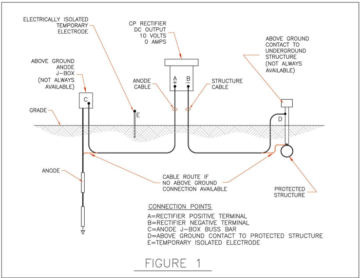
There are many physical configurations of CP systems. Variations in the location of the anode bed, the type of anode construction (deep well or shallow) and method of connection to the structure must be considered when selecting a testing method. Figure 1 below illustrates a few common configurations that will be addressed below.
Test Method 1
This test method applies to a CP system that includes a deep well anode system, anode junction box and an above ground appurtenance, electrically common with the protected structure. For this example, we will assume that the indicated voltage output of the Rectifier is about 10 Volts.
- With the rectifier “ON”, measure the DC voltage between point A & C and points B & D.
- If the positive (anode) cable is broken the readings would be:
- A & C – Approximately 9 Volts
- B & D - 0 Volts.
- If the structure cable is broken, the readings would be:
- A & C - 0 Volts
- B & D – Approximately 9 Volts.
- If both cables are broken, you will likely obtain many voltage readings that do not make sense. Therefore, Methods 2 & 3 will help.
Test Method 2
In this instance, there are no above ground connection points for either anode or structure cables.
- Switch “OFF” the rectifier.
- Find or establish an electrically isolated temporary test electrode/anode. This can be any number of structures including a chain link fence, barbwire fence with metal posts, a metal signpost or similar. If these are not available, you can drive a metallic test rod into the soil, like the one depicted in the drawing.
Important Note: To be effective, the test rod should be driven to a depth of at least 18” to 24”.
- To test the anode cable, connect a test cable between points A & E.
- While watching the rectifier ammeter, switch “ON” the rectifier. Watch for any amount of current output. Note that it will be a small amount. If any current output is indicated, this confirms that the anode (positive) cable is broken and the structure (negative) cable is okay.
If the test results indicate zero current output when the temporary anode/electrode is connected, it can mean:
- The structure cable is broken
OR
- Both the anode and the structure cables are broken. You must now test the structure (negative) cable.
- Connect a test cable between points B & E.
- While watching the rectifier ammeter, switch “ON” the rectifier.
- If any current output is indicated, this confirms that the structure (negative) cable is broken and the anode (positive) cable is okay.
Test Method 3
If the above tests indicate that both the positive and negative cables are broken, conduct the following test:
- Switch “OFF” the rectifier.
- Connect a test cable between points A & E.
- Connect a test cable between point B and the rectifier enclosure ground lug (not indicated on drawing).
- While watching the rectifier ammeter, switch “ON” the rectifier. You will be looking for any amount of current output. In this case, if any current output is indicated, this confirms that the anode (positive) cable AND the structure (negative) cables are both broken.