In cathodic protection (CP), a Four Point (Pin) Soil Resistance Meter (FPSRM) is used to measure the resistivity of the soil in the field or in a soil box. Common models include the M.C. Miller 400A and the Tinker & Rasor SR-2.
The Meter
The meters are basically an ohmmeter, albeit a special one. As the name implies, the meter has four points (pins) to obtain the needed resistance values.
Operation
Powered by internal batteries, a current is circulated between the C1 & C2 current terminals while measuring the voltage/potential drop between the P1 & P2 potential terminals. Using Ohm’s Law (R=E/I), the internal electronics are calibrated to provide a direct reading in ohms. Typically, these meters can accurately measure resistances from 0.01 ohms to 1.1 megohms.
These models differ from a standard ohmmeter, such as a Fluke 87 or similar, which cannot be used to obtain soil resistance measurements. This is because:
- The FPSRM uses a reversing polarity (modified square wave) current output with a frequency of 97Hz. This cancels out any electrode polarization of the soil pins that would result if a straight DC current source was used, i.e., a typical ohmmeter or digital multimeter (DMM).
- A DMM uses only two test leads to carry both the test current and measure the voltage drop. The resistance of the test leads and any contact resistance in the connections will be added to the final reading displayed. Therefore, the reading from a typical DMM can have a significant error when measuring resistances below 10Ω.
Uses of the FPSRM
The most common uses of a soil resistivity meter include:
- Determining the average soil resistivity to a specific soil depth
- Measuring the resistance-to-earth of a buried electrode, such as an anode or ground rod
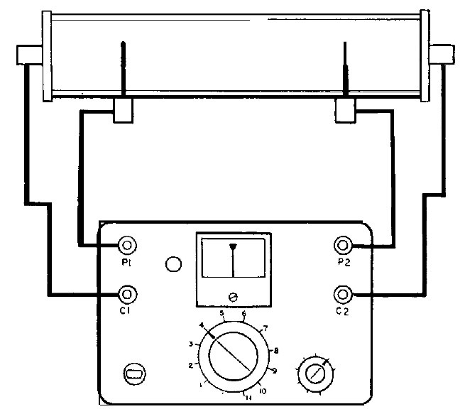
- Determining the resistivity of a soil sample or water sample when utilizing a “soil box”
- Measuring the resistance between two buried electrodes, such as two ground rods or two anodes
- Measuring the electrical resistance of a length of pipe or cable
In corrosion control, the most common use of the FPSRM is for measuring soil resistivities in the field using the "Wenner Four-pin Method.” The “Wenner” method consists of driving four metallic pins into the soil. The distance between each pin is equal to the depth of the soil to be measured. The following will provide the best results:
- The pins should be equal distance apart and in a straight line.
- Avoid installing the pins near any underground metallic structures. At a minimum, the pins should be installed at an offset and perpendicular to any known buried metallic structures or pipelines.
- If the soil is dry, wetting the soil around the driven pins may help. Specifically, the C1 & C2 pins are the most important pins for moisture.
- Each soil pin shall have a dedicated wire to interconnect the pin to the appropriate connecting post on the meter.
- Note and record the surface soil conditions, i.e., dry, damp, and previous weather conditions (recent rain, etc.) This information will be helpful in evaluating the overall resistivity profile.

Measuring and Calculating Soil Resistivity (4-Pin Wenner Method)
Following the manufacturer’s recommended operating procedures, manipulate the main knob of the meter to indicate a “Null” reading. Record the resistance (ohm) value and the multiplication factor, i.e., Null dial reading = 4.6Ω and the ohms “multiply by factor” = 1.0. Therefore, the total resistance measured = 4.6Ω.
Note: This is not the soil resistivity.
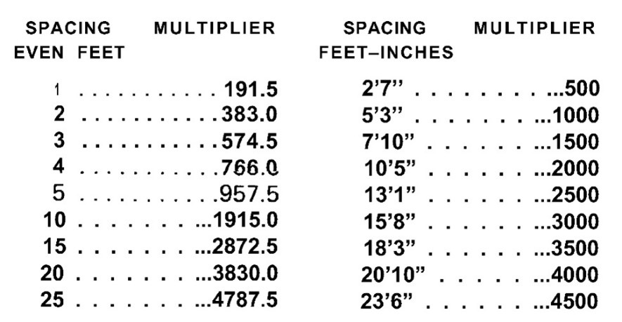
To calculate the soil resistivity for a pin spacing of 10 feet, use the following formula:
SR = 191.5 x D x R – Where:
- SR = Average resistivity in ohm-cm to depth in feet
- D = Distance between pins in feet
- R = Resistance in ohms as measured on the meter
Using the example above: 191.5 X D (10 ft.) X R (4.6Ω)
SR= 191.5 10 X 4.6 = 8,809 ohm-cm
The soil resistivity values measured using the four-pin resistivity method vary greatly between depths. It is important to remember that the soil resistivity measured is a weighted average of the soils from the surface to that depth.
NOTE: The table below shows two sets of pin spacings. The column to the right shows distances that use multipliers that are easier to work within the field.
Testing with a Soil Box
Soil samples obtained in the field can be tested in a “Soil Box.” An advantage to using a soil box is that results are precisely the value of the soil as tested. It is important to note the relative moisture content of the sample, as any soil that is dry will yield a high resistivity value. The soil box allows you to add moisture (distilled water) to the sample and compare the soil characteristics between dry and saturated. Soils with high parts per million chemical elements will show a significant drop in resistivity when saturated. This gives the CP technician an indication of the “worst case condition,” i.e., low resistivity usually equates to high corrosivity.
Facts about soil resistivity testing
- Obtaining soil samples in the field can be challenging, as a field technician will not usually have the necessary equipment to obtain a proper soil sample. Taking a sample with a shovel will NOT be representative of the soil at depth and will provide erroneous readings. Therefore, it is best to obtain soil samples from soil borings.
- On construction sites where engineered soils or cut-and-fill techniques are used, it is important to ensure that the samples you receive are representative of the soils that would be in contact with the pipeline or structure.
- On new pipeline installations, backfill material is often imported, such as sand or slurry. This must be considered when developing an anode design. If possible, specify that CP anodes are to be installed in undisturbed native soil. Installing anodes in sand or slurry will likely reduce the current output of the anodes due to the relatively higher resistivity of the sand or slurry environment.
- Be selective with the soil that you put in the soil box. Remove large clumps or rocks from the soil sample.
- Soil samples must be compacted in the soil box. Non-compacted soil will yield a much higher resistivity.
- You must fill the soil box completely to the top of the box to obtain an accurate reading.
- Make note of the type and color of the soil, i.e., clay, sand, loam, etc.
- Always note the relative moisture content of the "as received" sample, i.e., dry, trace of moisture, damp, wet, saturated.
- To obtain a “minimum resistivity,” it is necessary to add distilled water to the soil sample in the box. When adding distilled water to saturate the sample, note how well the water is absorbed. If the soil is reluctant to saturate the soil, you will have to wait for the water to migrate through the sample. If necessary, add more water to the sample so it becomes fully saturated. In some cases, you may have to allow the sample to soak overnight to obtain full saturation. If you test the resistivity periodically through the saturation process, you will see that the resistivity will continue to drop to a point where it stabilizes.
- Most soil boxes manufactured today have a 1:1 multiplier and use a “mini” version of a 4-pin method. Some of the older soil boxes (made by Agra) had 2:1 and even a 10:1 multiplier. These older boxes were built with two end plates and no potential pins, which is not ideal. Be sure and understand the type of soil box in use and the correct measurement process.
Advantages of Testing Actual Soil Samples in a Soil Box
- The reading obtained is the actual value of the soil at the depth and condition found in the field. There is no “averaging” of the reading.
- The ability to obtain a saturated value compared to the “as received” value helps better understand the soil characteristics.
- Soil samples can be lab tested for many other chemical properties if required.
Resistance-to-Earth of a Single Electrode
(Known as the “3 pin method” or “Fall off potential method”)
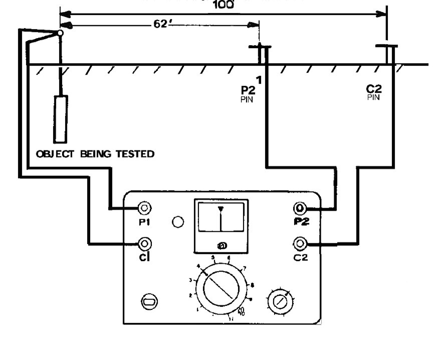
This method (often referred to as an “Electro-Log”) is typically used during the installation of a single anode or multiple anodes in a deep well anode bed.
Note the pin spacing and ratio. The potential pin is 62% of the total distance between the anode under test and the C2 pin. The 100 feet shown would be typical for a 20 feet deep electrode. It is important to have adequate pin spacing from the electrode under test not to influence the reading.
Once the pins are in place, the reading will be “Ohms to Earth” of the electrode being tested.
MISUSE OF THE FPSRM
What is wrong with these diagrams?
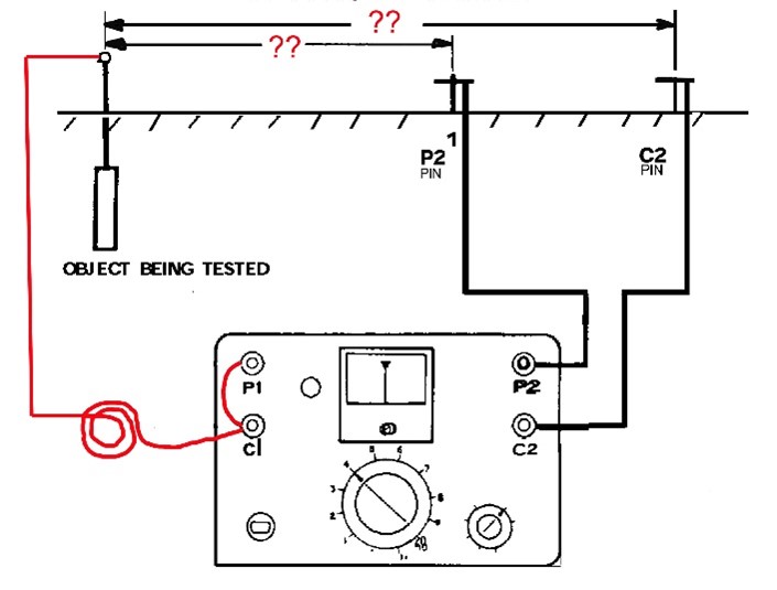
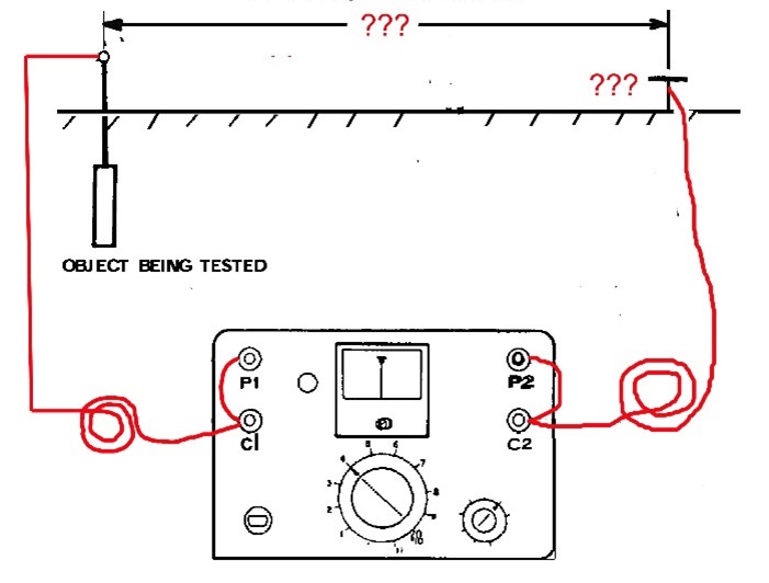
FIGURE A FIGURE B
FIGURE A & B = Test leads should NOT be on spools as indicated in the drawing. The “square wave” current output of the FPSRM will generate an inductive reactance that will add to the actual resistance being measured. This can result in a significant error and must be avoided.
FIGURE A & B = Interconnecting C1 & P1 as well as C2 & P2 with a short buss wire is often done to minimize or simplify the field wiring setup. However, the resistance of the test cable going to the anode or ground pin will add to the actual resistance of the electrode(s) under test.
Testing Cable Resistance
This method can provide very accurate results if performed properly. It is important that the cable under test is NOT coiled or on a spool.
FIGURE C – The improper method to be avoided. Even though there are four individual test leads, the figure shows the test leads “stacked” or connected to a common point on the cable under test. Any contact resistance between the test wires to the cable will add to the actual cable resistance.
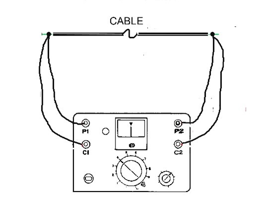
FIGURE C
FIGURE D – This shows the proper method of connecting the test leads to the cable under test. Separate C1 & C2 are positioned on the outside of P1 & P2. The actual cable resistance is the length of cable between P1 & P2.
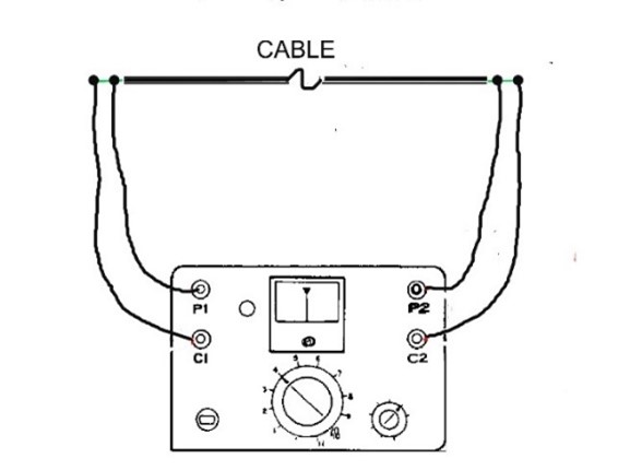
FIGURE D
NOTE: When measuring cable resistance with the FPSRM, the cable should not be on a spool or coil. The square wave current output of the FPSRM will generate an inductive reactance that will degrade the accuracy of the test.
Summary
The four-pin soil resistance meter is a versatile tool for accurately measuring soil resistivity, electrode-to-earth resistance values, the resistance of non-coiled cables as well as pipeline lengths. As with any technical instrument, knowing how to properly operate the device and why you are using a certain technique or test method is important. Understanding the limitations of the instrument and improper test methods will avoid obtaining erroneous data.
Farwest Corrosion Control Company
888-532-7937 FarwestCorrosion.com
Headquarters: 12029 Regentview Avenue, Downey, CA 90241
Los Angeles | Bakersfield | San Francisco | Seattle | Denver |Phoenix | Tulsa | Houston | Chicago | Philadelphia
© 2023 Farwest Corrosion Control Company. All Rights Reserved.
