Many cathodic protection (CP) technicians struggle with the proper way to read and interpret shunt measurements or readings.
The Basics
A shunt is a calibrated resistor of a known value, which is connected in series within an electrical circuit. By measuring the voltage across the shunt (mathematical formula used to calculate the relationship between current, voltage, and resistance: Ohms Law), the magnitude of current flowing within the circuit can be calculated.
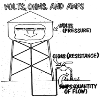
Because we cannot physically see volts, amperes or resistance, a comparison to something familiar like a water/hydraulic circuit, is being used to demonstrate the relationship.
|
Value |
Water Circuit |
Electrical Circuit |
|
Pressure |
Pounds per square Inch (PSI) |
Voltage (Volts) |
|
Flow |
Gallons per hour (GPH) |
Current (Amperes or Amps) |
|
Resistance to Flow |
Pipe size or friction loss |
Resistance (Ohms) |
In both water and electrical circuits, the three circuit values shown can be directly compared for cause and effect.

With high pressure/high water level and low resistance, (the water valve is open all the way), we can obtain a large current or water flow.
The same high pressure with a high resistance or friction loss (the water valve is nearly closed) will result in a lesser current or water flow.
A smaller pressure (lower water level) in either of the preceding instances will result in a correspondingly lower water flow.
Ohm’s Law defines the following electrical phrases and symbols as:
- Volts (V) = Electromotive Force
- Amperes (I) = Current Flow
- Ohms (R) = Resistance to flow of current with the “Omega” symbol (Ω)
If any the above values are found in an electrical circuit, the third can be calculated by using Ohm’s Law. Using the symbols V, I & R, the formula is:
- V= IR or Volts = Current x Resistance

- I = V/R or Current = Volts /Ohms
- R= V/I or Resistance = Voltage/Current
If any two of the above values are found in an electrical circuit, the third can be calculated by using Ohm’s Law. Using the symbols V, I & R, the formula is:
- V= IR or Volts = Current x Resistance
- I = V/R or Current = Volts /Ohms
- R= V/I or Resistance = Voltage/Current
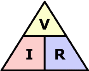
Use the diagram to the right to understand the formula: Put your finger on what you want to know, the remaining symbols reveal the formula you will use.
Example
To calculate the current flow in a circuit, use the formula I = V/R
- Measure voltage with a portable meter = 10.0 volts
- The resistance of the circuit is known and has a value of 2.0 Ohms (Ω)
- Therefore, the equation is 10.0 V/ 2.0 Ω = 5.0 Amperes
Important Note: It always best to use all whole unit numbers, i.e., volts, amps & ohms rather than mixing the values, i.e., millivolts and amperes in the same calculation. For reference:
- Volt = 1000 millivolts
- Ampere = 1000 milliamps
- Ohm = 1000 milliohms
Shunts and How to Use Them Properly
A shunt is a calibrated resistor with a known value. In cathodic protection, shunts are used for many applications. Some uses include:
- Measure the current output of an anode (galvanic or impressed current)
- Verify the accuracy of rectifier panel mounted ammeters
- Measure the current in pipeline resistance bond connections
The primary advantage of having a shunt in a circuit is to measure the current flow without disconnecting the circuit to install a portable ammeter. Clamp-on ammeters can be used in some instances. However, most are unable to accurately read current values of less than 200 milliamps (0.2 amps).
Shunts come in many sizes and ratings ranging from less than one ampere to thousands of amperes with varying resistance values. With the proper shunt in a circuit, you can determine the magnitude of current flow by using a typical digital multimeter (DMM).
Following are examples of commonly used shunts for cathodic protection:
 |
Holloway Type “SS”, 0.001 Ω with a 25-ampere rating. This shunt is very popular for use in impressed current anode junction boxes. |
 |
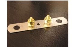
Holloway Type “RS”, 0.01 Ω with a 6-ampere rating. The RS is used in both impressed current and galvanic anode applications. |
| Note: Not all shunts have the resistance value inscribed on the shunt. The Holloway RS is one example of that. |
|
 |
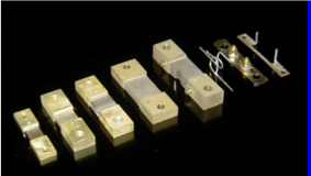
The five-shunt shown on the left is typically used in CP rectifiers. The shunt would be connected to the front panel ammeter.
The three smaller shunts on the right of the photo are commonly found in anode junction boxes or CP test stations. |
 |
The shunts to the left are popular in post-mounted test stations. They are color-coded to depict their resistance value. Red = 0.1 Ω Yellow = 0.01 Ω Orange = 0.001 Ω |
Note: All shunts will have 4 points of connection. Two positions to connect into the current circuit and two positions to be used to measure the voltage or millivolt value across the shunt.
When measuring the voltage drop across a shunt to determine current, it is imperative that you know the resistance value of the shunt and understand Ohm’s Law. In all cases, when measuring shunts for current values, the formula to use is I = V / R.
- I = The current value you need to know
- V = The voltage drop across the shunt test points (usually measured in millivolts)
- R = The known resistance of the shunt in ohms Ω
Note: The shunts used in the CP industry typically have very low resistance values, such as are 0.001 Ω, 0.01 Ω and 0.1 Ω.
Measurement Example 1: Shunt Resistance value is 0.001 Ω.
- With your meter setting on DC millivolts, you measure 5.3 millivolts (0.0053 volts) across the shunt.
- The resistance of the shunt is 0.001 Ω
- Therefore, the equation is 0.0053 / 0.001 = 5.3 Amperes
The benefit of using this shunt is the value you read in millivolts on your meter is a direct conversion to amperes.
Measurement Example 2: Shunt resistance is 0.01 Ω
- With your meter setting on DC millivolts, you measure 5.3 millivolts (0.0053 volts)
- The resistance of the shunt is 0.01 Ω
- Therefore, the equation is 0.0053 / 0.001 = 0.53 Amperes
Another way to think about this shunt is that the value of 10 millivolts on your meter will equal 1.0 amperes. Therefore, with your meter on millivolts, the reading is 5.3, so simply move the decimal point one position to the left to determine the current in Amperes.
Important Note: In the above measurement examples, the meter reading of 5.3 millivolts was the same. However, the actual current was a factor of 10 differential. Therefore, it is imperative for the technician to know the resistance value of the shunt.
